SICP - Solution: Exercise 2.3
January 5, 2019
Exercise 2.3 #
Implement a representation for rectangles in a plane. (Hint: You may want to make use of Exercise 2.2.) In terms of your constructors and selectors, create procedures that compute the perimeter and the area of a given rectangle. Now implement a different representation for rectangles. Can you design your system with suitable abstraction barriers, so that the same perimeter and area procedures will work using either representation?
Solution #
Let’s start by writing perimeter-rect and area-rect the way we would like to see them:
(define (perimeter-rect r)
  (* 2 (+ (width-rect r) (height-rect r))))

(define (area-rect r)
  (* (width-rect r) (height-rect r)))
Both of this functions rely on basic characteristics we can expect that any public interface for a rectangle should provide.
It is interesting to note that the problem doesn’t require for the constructors to be part of the public interface. We won’t try to make generic constructors that abstract the representation.
From the definition of the exercise, we can’t assume that the segments of the rectangle will be parallel to the axis, but this is a relatively minor point as the main goal here is to make us think about public interfaces and abstraction barriers.
Since both implementations will rely on points, we can share this code with a few helper functions:
(define (make-point x y) (cons x y))
(define (x-point p) (car p))
(define (y-point p) (cdr p))

(define (distance-point p1 p2)
  (sqrt
   (+ (sqr (- (x-point p1) (x-point p2)))
      (sqr (- (y-point p1) (y-point p2))))))

; Looks like vectors...
(define (dot-product p1 p2)
  (+ (* (x-point p1) (x-point p2))
     (* (y-point p1) (y-point p2))))

(define (add-vector v1 v2)
  (make-point (+ (x-point v1) (x-point v2))
              (+ (y-point v1) (y-point v2))))

(define (sub-vector v1 v2)
  (make-point (- (x-point v1) (x-point v2))
              (- (y-point v1) (y-point v2))))
First representation #
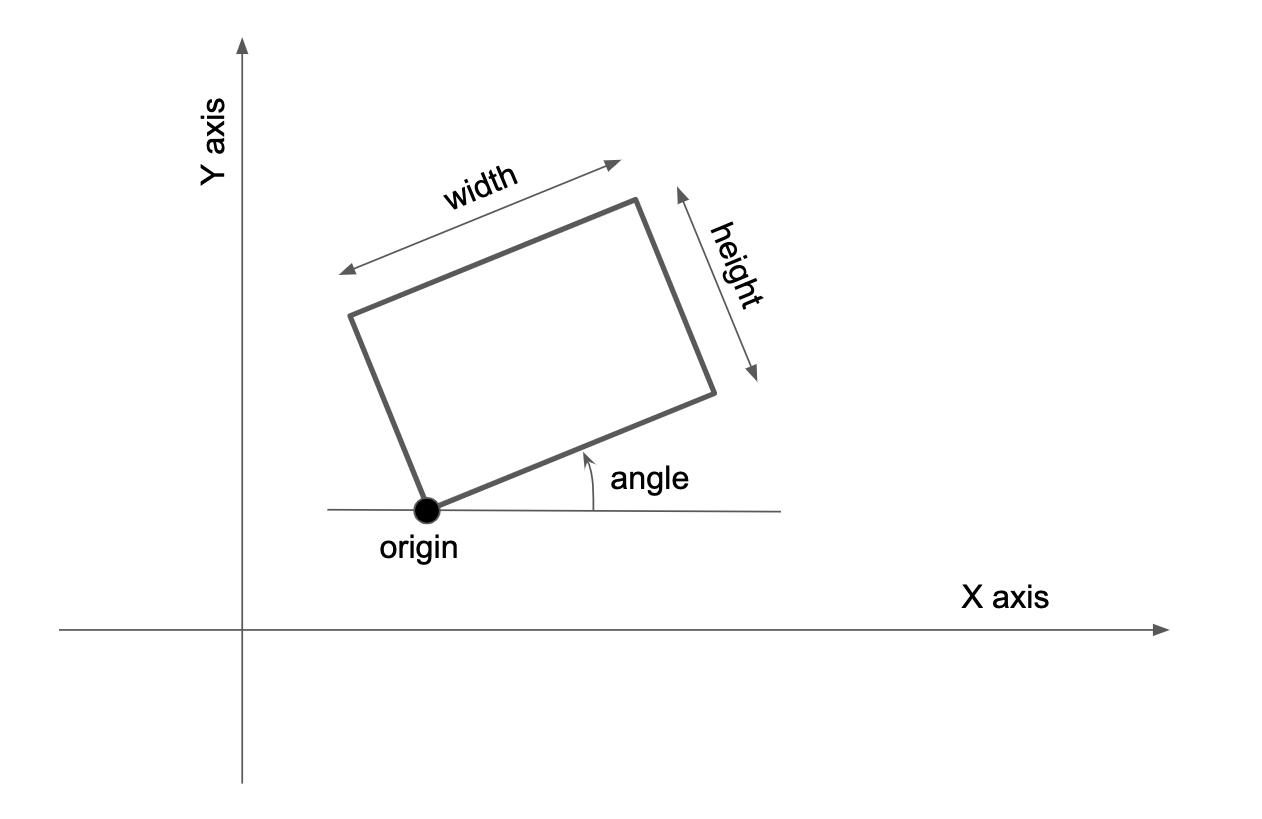
We can imagine a first representation that specifies corner points, height, width and angle. This representation has 5 degree of freedom (2 dimensions for the corner points, then one for each dimension) and is the minimal needed to specify the rectangle:

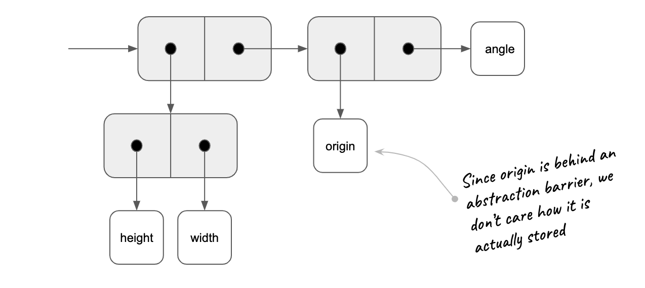
One way of storing this information into cons is:

From this, the implementation would be:
(define (make-rect origin height width angle)
  (cons (cons height width) (cons origin angle)))

(define (origin-rect r) (car (cdr r)))
(define (angle-rect  r) (cdr (cdr r)))

; Public interface
(define (height-rect r) (car (car r)))
(define (width-rect  r) (cdr (car r)))
Based on that, we can test our solution by building rectangle 1:
(define origin1 (make-point 1 1))
(define height1 4.0)
(define width1 5.0)
(define angle1 0.2)

(define r1 (make-rect origin1 height1 width1 angle1))

(display "Rectangle 1: ") (newline)
(display "Perimeter: ") (display (perimeter-rect r1)) (newline)
(display "Area ") (display (area-rect r1)) (newline) (newline)
That will display:
Rectangle 1:
Perimeter: 18.0
Area 20.0
Second representation #
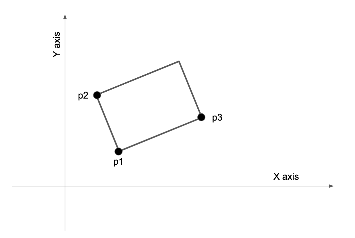
Another representation can be specifying three corners out of the four. This representation has 6 degrees of freedom (2 dimensions of each points). It means that it could also represent losange shape. We need to add a constraints so that the angle $\widehat{p1 p2 p3}$ is a right angle. Here is what it looks like:

One way of storing this information into cons is:

From this, the implementation would a little more complex, has we need to add the mechanism to check for orthogonality:
; Helper
(define (dot-product p1 p2)
  (+ (* (x-point p1) (x-point p2))
     (* (y-point p1) (y-point p2))))

(define (add-vector v1 v2)
  (make-point (+ (x-point v1) (x-point v2))
              (+ (y-point v1) (y-point v2))))

(define (sub-vector v1 v2)
  (make-point (- (x-point v1) (x-point v2))
              (- (y-point v1) (y-point v2))))

(define (orthogonal? v1 v2)
  (= 0.0 (dot-product v1 v2))) ; should it be better with an small range?

; Constructor
(define (make-rect p1 p2 p3)
  (if (orthogonal? (sub-vector p2 p1) (sub-vector p3 p1))
      (cons p1 (cons p2 p3))
      (error "Points should make an rectangle."))) ; check orthogonality, which is longer? (error "Argument not 0 or 1: CONS" m)

(define (p1-rect r) (car  r))
(define (p2-rect r) (car (cdr r)))
(define (p3-rect r) (cdr (cdr r)))

; Public interface
(define (height-rect r) (distance-point (p1-rect r) (p2-rect r)))
(define (width-rect  r) (distance-point (p1-rect r) (p3-rect r)))
Based on that, we can test our solution by building rectangle 2:
(define p4 (make-point 0 0))
(define p5 (make-point 10 -2))
(define p6 (make-point 1 5))

(define r2 (make-rect p4 p5 p6))

(display "Rectangle 2: ") (newline)
(display "Perimeter: ") (display (perimeter-rect r2)) (newline)
(display "Area ") (display (area-rect r2)) (newline) (newline)
That will display:
Rectangle 2:
Perimeter: 30.594117081556707
Area 51.99999999999999
Cross testing rectangle 1 using the three points representation #
To check our implementation, it would be nice to see that rectangle 1 when transformed into the second representation gives the same results. It can be done with a little bit of math:
(define origin1 (make-point 1 1))
(define height1 4.0)
(define width1 5.0)
(define angle1 0.2)

;(define origin (make-point 0 0))
;(define height 10.198039027185569)
;(define width 5.09901951359278455)
;(define angle -0.19739555984988078)

(define (rotate-origin p a)
  (let ((x (x-point p))
        (y (y-point p)))
    (make-point (- (* x (cos a)) (* y (sin a)))
                (+ (* y (cos a)) (* x (sin a))))))

(define p1 origin1)
(define p2 (add-vector origin1 (rotate-origin (make-point 0 width1)  angle1)))
(define p3 (add-vector origin1 (rotate-origin (make-point height1 0) angle1)))

(define r1 (make-rect p1 p2 p3))

(display "Rectangle 1: ") (newline)
(display "Perimeter: ") (display (perimeter-rect r1)) (newline)
(display "Area ") (display (area-rect r1)) (newline) (newline)
The results:
Rectangle 1:
Perimeter: 18.0
Area 20.0
Cross testing rectangle 2 using the origin, width, height and angle reprensentation #
Again, lets change reprensentation and check the results:
(define p4 (make-point 0 0))
(define p5 (make-point 10 -2))
(define p6 (make-point 1 5))

(define origin2 p4)
(define height2 (distance-point p4 p5))
(define width2  (distance-point p4 p6))
(define angle2  (atan (/ (y-point p5)
                         (x-point p5))))

(define r2 (make-rect origin2 height2 width2 angle2))

(display "Rectangle 2: ") (newline)
(display "Perimeter: ") (display (perimeter-rect r2)) (newline)
(display "Area ") (display (area-rect r2)) (newline) (newline)
Gives as results:
Rectangle 2:
Perimeter: 30.594117081556707
Area 51.99999999999999
Conclusion #
There is no “best” representation here. It all depends on what you want to do.
We could also add more constructors that will allow to use both specification as input and hide the real implementation.